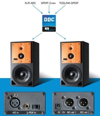
KS Digital DDC- Digital-Digital-Converter

 $ 650 предложить свою цену
45262
DDC serves signal processing and to split digital signals. Three inputs with different formats (XLR-AES, SPDIF-Coax and optical TOSLINK-SPDIF) enable the connection of all common digital sources. Two outputs in AES format to XLR jacks / connectors drive even long cables to the monitors and thus prevent feedback and the sound being jeopardised.
DDC function: The circuit scans the different inputs (AES, SPDIF, TOSLINK) and routes the input to the signal processor, which is the first to drive a valid signal. If this breaks off, the scan procedure begins anew. During this process the sample frequency of the input signal is determined (measured) and the output circuit then synchronises it. What is thereby decisive for the quality and integrity of the data is a built-in high precision master clock, which supplies the output drivers. The outputs are thus guaranteed a highly stable and clean (low jitter) clock. This is not a classic sample rate convertor circuit board that follows the PLL with output sample rate and ultimately picks up its fluctuations and jitter. The outputs here lie electrically parallel and deliver signals independently of each other. The DDC is a real problem solver for all signal converting processes and / or too long digital cables with false impedance, and much, much more.
